


How to handle PLC malfunctions? Sanchang Intelligence guides you through troubleshooting and resolution
Category: Technical Classroom
2025-09-25
In PLC control systems, the site is a high-risk area for faults, mainly concentrated in the following types of equipment or links:
1. Relays and contactors (with many faults)
In the daily maintenance of production line PLC, electrical components such as relays and air switches consume a large amount. In addition to product quality, the harsh environment on site (such as dust and humidity) is the main cause, and the contactor contacts are prone to ignition, oxidation, and ultimately failure. Choosing a well sealed control box can significantly extend the lifespan of internal components; Prioritizing high-performance relays and improving the usage environment can reduce replacement frequency and minimize the impact on the system.
2. Valve and gate equipment
This type of equipment has a large displacement of the actuator and a complex transmission structure (involving mechanical, electrical, and hydraulic systems). If not maintained for a long time, it is prone to problems such as jamming and leakage. It is necessary to strengthen inspections, establish strict inspection systems, regularly check valve body deformation, actuator flexibility, and controller effectiveness to ensure the normal operation of equipment.
3. Switches, limit and protection components
Long term wear and tear or idle rusting can lead to malfunctions, such as the proximity switch of the cloth walking vehicle in the kiln tail material ball storage, which is prone to contact deformation, oxidation, or blockage due to frequent movement and high dust, resulting in poor contact. Regular maintenance is required, and heavy equipment limit switches also need to be designed with multiple protections.
4. PLC sub devices (junction boxes, terminals, etc.)
The causes of faults include equipment process defects and installation issues (such as excessive tightening of wire screws, which can easily damage parts during maintenance), as well as long-term ignition and corrosion, which can also cause faults. Installation and maintenance must strictly follow the process requirements to avoid potential hazards. Such faults are difficult to detect and require extra attention.
5. Sensors and Instruments
Faults often manifest as abnormal signals. During installation, it is necessary to ensure that the shielding layer of the signal line is reliably grounded at one end and laid separately from the power cable (especially the output cable of the frequency converter). Software filtering is also required inside the PLC. Signal problems found during daily inspections should be promptly addressed.
6. Interference from power, ground, and signal lines
It is necessary to combine engineering design experience and daily maintenance observation for improvement, while paying attention to factory processes and safety operating procedures, maintaining the control room environment, and avoiding excessive optimization of single links or the use of complex control methods (contrary to economic and practical principles) to prevent an increase in failure rates.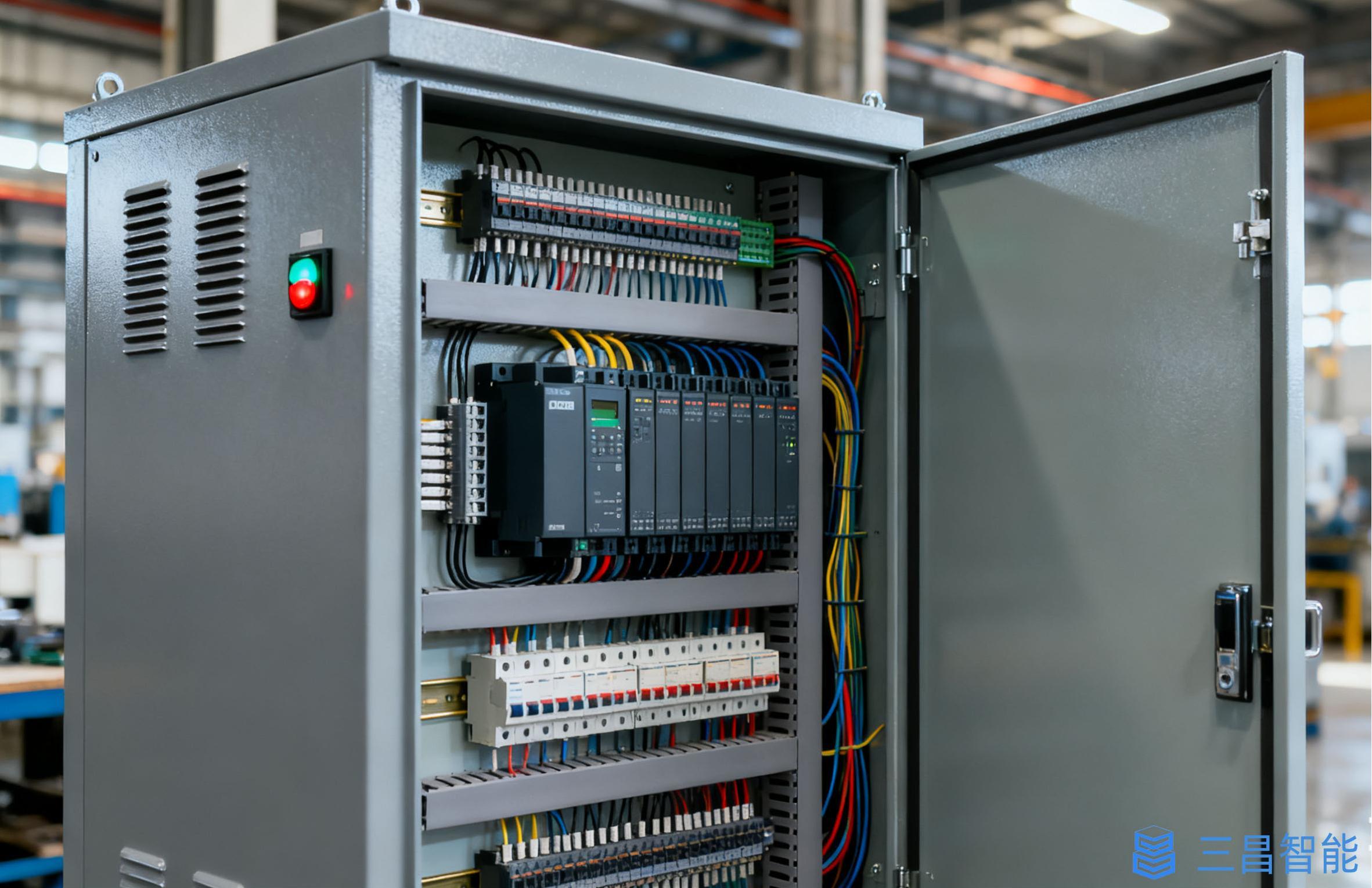
Solution to PLC malfunction problem
PLC itself has high reliability, and faults are mostly caused by peripheral operations or components. The specific solutions are as follows:
1. PLC self fault diagnosis
The probability of PLC hardware (such as CPU) and software failure is extremely low, and the input points are not easily damaged unless there is strong electrical invasion, and the output relay contacts are not short circuited or exceed the rated current of the load. During maintenance, priority should be given to investigating peripheral electrical components rather than suspecting the PLC itself, in order to quickly restore production.
2. Selection of Input/Output (I/O) Modules
Transistor type module has fast switching (0.2ms) but low load (0.2~0.3A, 24VDC), suitable for high-frequency signals; Controllable silicon type contactless, suitable for AC small loads; Relay type AC/DC universal, high load (10ms switching speed), preferred for conventional control to avoid high-frequency scenarios.
3. Grounding issue
PLC requires independent dedicated grounding, and related equipment also needs to be reliably grounded to avoid interference current caused by multiple grounding points. Analog signals can use shielded floating ground technology (single point grounding of the shielding layer, circuit insulation resistance ≥ 50M Ω) to prevent common mode interference.
4. Inter line capacitance interference
When the capacitance between cables exceeds the limit, it is easy to cause PLC input misoperation (such as correct wiring but no input, input interference). It is necessary to use twisted core cables, shorten the length, separate interference input cables, or use shielded cables to reduce the impact of capacitance.
5. Anti interference processing
Double layer shielded cables are used for analog signals, and high-speed pulse signals and PLC communication cables (preferably manufacturer's dedicated lines or shielded twisted pair cables) need to be shielded; Analog/DC signal lines and AC signal lines are laid in separate slots, and shielded cables are directly connected to equipment; Power cables and signal cables are laid separately. Interference can be resolved on-site by re laying shielded cables and adding filtering codes to the program.
6. Mark input and output for easy maintenance
Create an input/output terminal table (labeled with numbers, electrical symbols, and Chinese names) based on the electrical schematic diagram and attach it to the control cabinet; For personnel who are not familiar with operations or ladder diagrams, create additional logic function tables (explaining input/output logic relationships) to improve maintenance efficiency.
7. Inferring faults through program logic
Low end PLC ladder diagram instructions are similar, while mid to high end machines (such as S7-300) may use language tables for programming, and the program needs to have Chinese annotations. The reverse deduction method is used for maintenance, and the logical relationship of the output relay is traced back from the fault point. The probability of multiple faults in the equipment is low, and finding one fault can usually eliminate the problem.
8. Fully utilize software and hardware resources
Instructions that do not participate in the control loop are not connected to the PLC; When multiple instructions control the same task, connect it to a single input point after external parallel connection; Use more internal software components to reduce hardware investment; Independent output circuit for easy maintenance; The forward and reverse control of the load requires dual internal and external interlocking; Emergency stop is cut off with an external switch to ensure safety.
9. Other precautions
The AC power cord is not connected to the input terminal; The grounding terminal is independently grounded (not in series), and the ground wire is ≥ 2mm ²; The auxiliary power supply only drives low-power devices (such as photoelectric sensors); Do not connect the PLC empty address terminal; When the output circuit is unprotected, external series fuses are used to prevent load short circuits.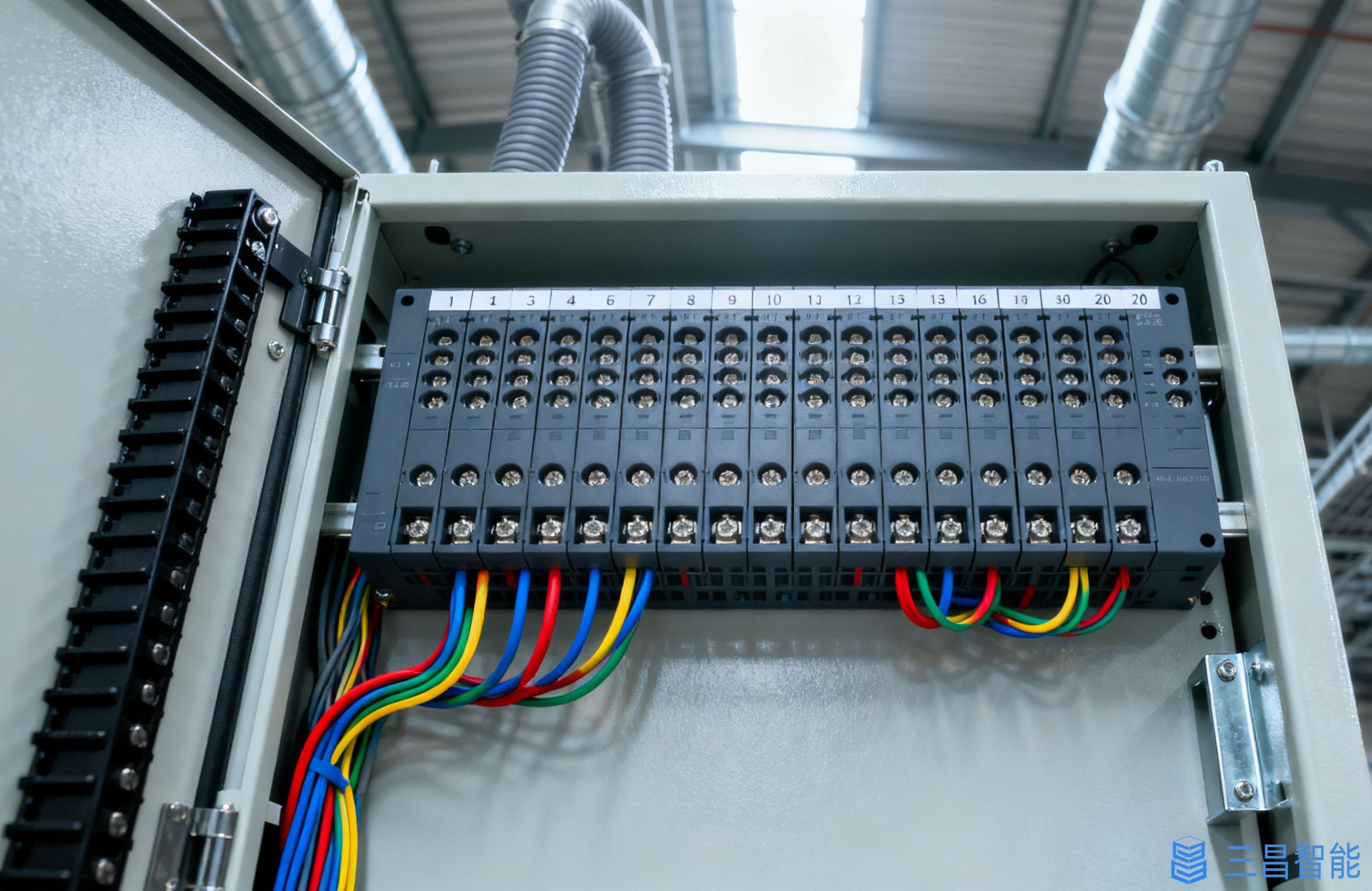
RELATED INFORMATION


Dedicated to provide customers with quality products and timely and thoughtful service
Contact Information
Sales Hotline: 00-86-0731-52265588
86-17673181870
E-mail:SCZN126@126.com
Enterprise address: No.8, South Side of Tianma East Road, Yishuhe Town, Xiangtan County, Xiangtan City, Hunan Province